Updated: 2009-09-20, 2022-02-10
Overview
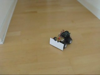
I wanted to make a small robot that could sense its surroundings and wander around by itself. I used a toy RC car, an Arduino microcontroller, and light and temperature sensors.
Video

Pictures
There are more pictures, some with annotations, here.
Hardware
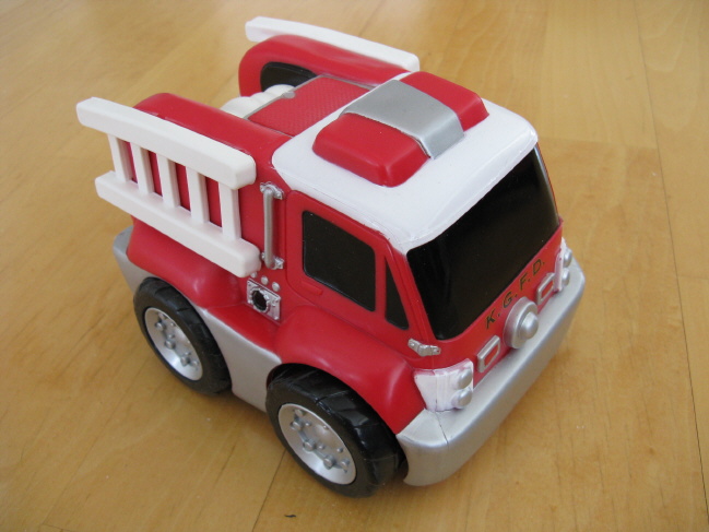
I started out with this toy RC car from Kid Galaxy:

I chose that car because it can spin in place by driving its wheels in opposite directions. That makes it much easier to steer than other cheap RC cars with crappy front-wheel steering, even though it can only turn in one direction.
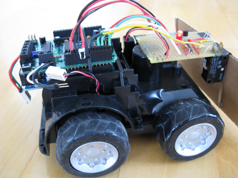
I took out the radio-control electronics and replaced them with an Arduino microcontroller and an Adafruit Motor Shield. I added a few other parts:
- A CdS photocell light sensor
- An LM35 temperature sensor
- A bump switch to detect obstacles
- An LED activity indicator
Click here for a breadboard diagram of how the sensors are hooked up to the Arduino. (This doesn’t show the Motor Shield and motor connections.)
I had to remove the car body and hack up the chassis a bit, and here’s what I ended up with. (Click for an annotated version of the picture.)

Everything connected to the Arduino can be unplugged easily, in case I need to use the Arduino for something else (because I don’t have any spare Arduini). I made this easier by using some of the Arduino’s analog input pins as digital pins, for the LED and the bump switch. That let me plug most of the wires from the sensor board into one header block.
There are two separate power supplies. The 3 AA cells that originally powered the toy car are still used to run the motor, and a 9V battery powers the Arduino. I find this inconvenient. There are too many batteries to replace and the 9V doesn’t last very long. With the Motor Shield it’s usually a good idea to use separate power supplies for the motors and the Arduino, but I think a common supply would be OK with the one small DC motor I’m using. Unfortunately the 4.5 V supply for the motor isn’t enough for the Arduino.
Behaviour
I wrote an Arduino sketch to control ToyBot’s behaviour, using input from the light, temperature and bump sensors. Its basic behaviour is to drive toward an area of bright light. If it gets too hot, it heads for a shady area instead. (Basically, ToyBot acts like a cat.)
The behaviour rules are:
- Find the direction where the brightest light is, by spinning in place while monitoring the light sensor.
- Drive toward the light.
- When the light gets dimmer, stop and scan again to find where the light is.
- If the temperature gets too high, change the above behaviour to seek darkness instead of light.
- If the bump switch detects that the bot has hit something, turn around and head in the opposite direction.
- If the bot spins around without finding a particularly bright (or dark) direction to go, it goes to sleep.
- If the bot only drives a short distance several times in a row, it goes to sleep. (This stops it if it’s moving around in a small patch of light.)
- If the bot is sleeping, it wakes up when there’s a significant change in brightness or temperature.
The LED activity indicator lights up or blinks to indicate what the bot is doing.
Here is the source code for the Arduino sketch that controls ToyBot’s behaviour.
